Control an 8x8 matrix of LEDs.
Blog post description.
7/2/20243 min read
Row-column Scanning to control an 8x8 LED Matrix.
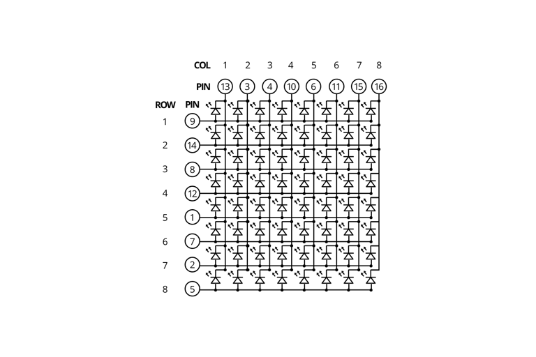
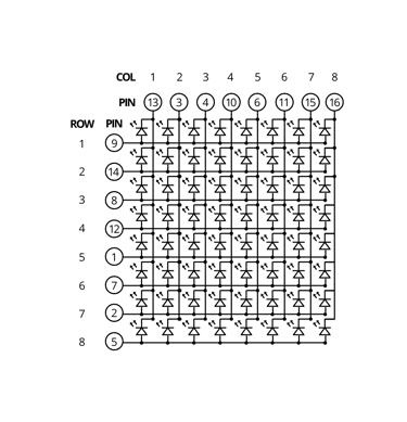
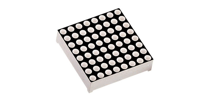
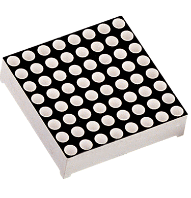
LED displays are often packaged as matrixes of LEDs arranged in rows of common anodes and columns of common cathodes, or the reverse. Here's a typical example, and its schematic:
These can be very useful displays. To control a matrix, you connect both its rows and columns to your microcontroller. The columns are connected to the LEDs cathodes (see Figure 1), so a column needs to be LOW for any of the LEDs in that column to turn on. The rows are connected to the LEDs anodes, so the row needs to be HIGH for an individual LED to turn on. If the row and the column are both high or low, no voltage flows through the LED and it doesn't turn on.
To control an individual LED, you set its column LOW and its row HIGH. To control multiple LEDs in a row, you set the row HIGH, then take the column high, then set the columns LOW or HIGH as appropriate; a LOW column will turn the corresponding LED ON, and a HIGH column will turn it off.
Tip - Pins set to OUTPUT by use of the PinMode command are set to LOW if not otherwise stated
Although there are pre-made LED matrices, you can also make your matrix from 64 LEDs, using the schematic
It doesn't matter which microcontroller pins you connect the rows and columns to, because you can assign things in software—connect the pins in a way that makes wiring easiest. A typical layout is shown below.
Here's a matrix of the pin connections, based on the diagram above:
Matrix pin no.RowColumnArduino pin number15-1327-123-2114-31058-16 (analog pin 2)6-517 (analog pin 3)76-18 (analog pin 4)83-19 (analog pin 5)91-210-4311-64124-513-16142-715-7816-89
Hardware Required
Arduino Board
8 x 8 LED Matrix
2x 10k ohm potentiometers
hook-up wires
breadboard
8x 1k ohm resistors
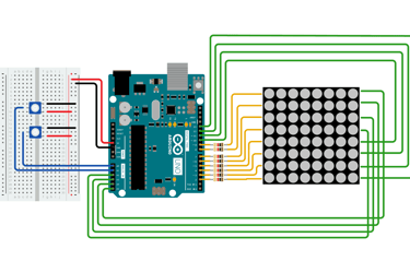
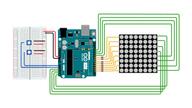
Circuit
The 16 pins of the matrix are hooked up to 16 pins of the Arduino board. Four of the analog pins are used as digital inputs 16 through 19. The order of the pins is assigned in two arrays in the code.
Two potentiometers, connected to analog pins 0 and 1, control the movement of a lit LED in the matrix.
To keep your LED matrix from burning, add 8 10kΩ resistors to the wires connected in yellow in the image below.
Circuit diagram of the LED matrix.
Schematic
Schematic of the LED matrix.
Code
/*
Row-Column Scanning an 8x8 LED matrix with X-Y input
This example controls an 8x8 LED matrix using two analog inputs
for the pin connections.
For other LED cathode column matrixes, you should only need to change the pin
numbers in the row[] and column[] arrays.
rows are the anodes
cols are the cathodes
---------
Pin numbers:
Matrix:
- digital pins 2 through 13,
- analog pins 2 through 5 used as digital 16 through 19
Potentiometers:
- center pins are attached to analog pins 0 and 1, respectively
- side pins attached to +5V and ground
// 2-dimensional array of row pin numbers:
const int row[8] = {
2, 7, 19, 5, 13, 18, 12, 16
};
// 2-dimensional array of column pin numbers:
const int col[8] = {
6, 11, 10, 3, 17, 4, 8, 9
};
// 2-dimensional array of pixels:
int pixels[8][8];
// cursor position:
int x = 5;
int y = 5;
void setup() {
// initialize the I/O pins as outputs iterate over the pins:
for (int thisPin = 0; thisPin < 8; thisPin++) {
// initialize the output pins:
pinMode(col[thisPin], OUTPUT);
pinMode(row[thisPin], OUTPUT);
// take the col pins (i.e. the cathodes) high to ensure that the LEDS are off:
digitalWrite(col[thisPin], HIGH);
}
// initialize the pixel matrix:
for (int x = 0; x < 8; x++) {
for (int y = 0; y < 8; y++) {
pixels[x][y] = HIGH;
}
}
}
void loop() {
// read input:
readSensors();
// draw the screen:
refreshScreen();
}
void readSensors() {
// turn off the last position:
pixels[x][y] = HIGH;
// read the sensors for X and Y values:
x = 7 - map(analogRead(A0), 0, 1023, 0, 7);
y = map(analogRead(A1), 0, 1023, 0, 7);
// set the new pixel position low so that the LED will turn on in the next
// screen refresh:
pixels[x][y] = LOW;
}
void refreshScreen() {
// iterate over the rows (anodes):
for (int thisRow = 0; thisRow < 8; thisRow++) {
// take the row pin (anode) high:
digitalWrite(row[thisRow], HIGH);
// iterate over the cols (cathodes):
for (int thisCol = 0; thisCol < 8; thisCol++) {
// get the state of the current pixel;
int thisPixel = pixels[thisRow][thisCol];
// when the row is HIGH and the col is LOW,
// the LED where they meet turns on:
digitalWrite(col[thisCol], thisPixel);
// turn the pixel off:
if (thisPixel == LOW) {
digitalWrite(col[thisCol], HIGH);
}
}
// take the row pin low to turn off the whole row:
digitalWrite(row[thisRow], LOW);
}
}