The Language of Power: Decoding the Four Essential Switchgear Drawings ⚡️
Blog post description.
11/1/20253 min read
The Language of Power: Decoding the Four Essential Switchgear Drawings ⚡️
For those navigating the intricate realm of electrical infrastructure—whether in a large data center, a manufacturing facility, or a contemporary substation—the switchgear acts as the core nervous system. It comprises crucial assemblies of circuit breakers, fuses, and protective relays essential for controlling, safeguarding, and isolating the entire electrical network.
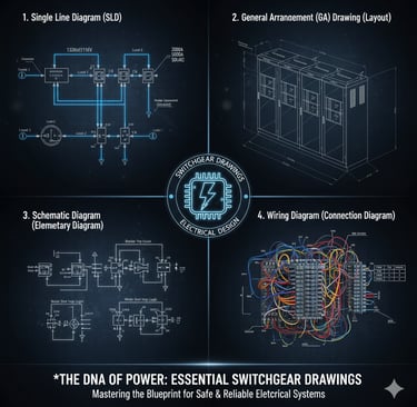
But how do we turn the concept of safe and dependable power into tangible hardware? By utilizing a precise set of blueprints. These four fundamental types of switchgear drawings constitute the digital DNA of your electrical design, ensuring that every component, connection, and operation are accurately depicted. Master these drawings, and you will master power system design.
1. The High-Level Map: Single Line Diagram (SLD) 🗺️
The Single Line Diagram (SLD) serves as the foundation for any electrical endeavor. It is consistently the first drawing created and the last one revised.
What It Is:
The SLD is a symbolic visualization of a three-phase system utilizing just one line. It eliminates physical details to emphasize solely the functional relationships and connectivity of the key components.
Its Critical Role:
The SLD is utilized to calculate and outline system specifications. It determines:
Power Flow: Tracking the flow of electricity from the utility source to the final loads.
Equipment Ratings: Specifying required voltage, current, and short-circuit capacity for transformers, busbars, and breakers.
Protection Strategy: Identifying the location, type, and function codes of all protective relays and metering devices.
If the SLD is inaccurate, the entire structural integrity of the electrical system is compromised. It is a vital instrument for system analysis and preliminary equipment selection.
2. The Physical Footprint: General Arrangement (GA) Drawing 📏
While the SLD addresses electrical theory, the General Arrangement (GA) Drawing confronts the physical aspects. It answers the question: Where should the switchgear be installed, and what are its dimensions?
What It Is:
The GA is a scaled mechanical illustration depicting the physical construction of the switchgear arrangement. It encompasses front, side, and top views, often including cross-sectional details.
Its Critical Role:
This drawing is crucial for collaboration beyond electrical engineering:
Civil & Structural Teams: Supplies overall dimensions, weight, and mounting points for room layout and foundational design.
Facility Engineers: Indicates necessary maintenance and operation clearances (e.g., door swing radius, space for breaker withdrawal) per standards like NFPA 70E.
Manufacturing: Outlines compartment layout, busbar design, and cable entry/exit locations.
The GA drawing guarantees that the switchgear can fit physically into the designated space and be safely accessed and maintained during its lifespan.
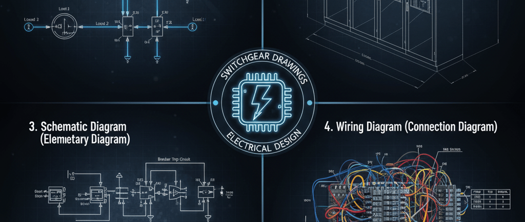
3. The Functional Logic: Schematic Diagram (Elementary) 🧠
The Schematic Diagram, also known as the elementary diagram, serves as the brain for the switchgear. It transcends power delivery to visualize the intricate control and protection logic.
What It Is:
This diagram employs standardized symbols to illustrate how all the low-voltage control components—such as relays, auxiliary contacts, pushbuttons, lamps, and circuit breaker mechanisms—connect to execute a specific function. Unlike the Wiring Diagram, the arrangement of components is not significant; the emphasis is placed purely on electrical function and sequence.
Its Critical Role:
Protection Design: It visualizes the tripping and closing circuits, ensuring that relays control the appropriate circuit breaker during fault conditions.
Automation Interface: It specifies contact connections necessary for interfacing with external systems like DCS (Distributed Control Systems) or PLC (Programmable Logic Controllers).
Troubleshooting: When a fault arises, technicians utilize the schematic to unravel the logic and pinpoint the component obstructing the proper operation.
The schematic represents the engineer's logic puzzle, defining the behavior of the switchgear.
4. The Build Guide: Wiring Diagram (Connection) 🧵
The final and most detailed level of information is captured in the Wiring Diagram, serving as an assembly guide for the switchgear manufacturer.
What It Is:
The wiring diagram details the point-to-point physical connection of each wire within the control panel. It denotes the precise terminal block number, wire color, and a unique wire number for every conductor.
Its Critical Role:
Manufacturing Quality: It serves as the primary document for panel wiremen to verify that the Schematic logic is physically executed accurately.
Installation: It specifies the external connections required for field cabling to connect to the switchgear's terminal blocks.
Maintenance: For technicians, this diagram is indispensable when replacing a component or isolating a specific wire during maintenance, as it removes any ambiguity regarding where a cable starts and ends.
The wiring diagram is where Digital Transformation (DX) converges with physical construction, translating abstract symbols into tangible copper wire.
Final Takeaway for Tech-DX 🚀
For effective project execution and streamlined operations, these four types of drawings must be regarded as a cohesive unit. In the era of IIoT and smart power grids, the digital accuracy of your SLD, GA, Schematics, and Wiring Diagrams establishes the foundation for everything from system modeling to predictive maintenance. Ensuring these blueprints are meticulously designed and maintained is not merely sound practice; it is essential for modern electrical excellence.